
It would be very useful to have an electronic
circuit that would:
An
electronic circuit that will do this is called a BISTABLE CIRCUIT.
This is a circuit that is
stable in one of two states and will not change its state until the other switch is pressed.
The
two inputs are made by two simple press Switches, labelled S and P and the output is Shown by
the two LEDs. The switches are high when they are open and low when they are closed. When
they are released they will spring open on their own, becoming high.
That may sound a
little difficult so we will look at how one version of a bistable circuit works.
The version that
we are going to use is made from two NAND gates connected together as shown in the circuit
below.
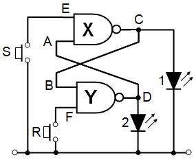
To start with suppose that C = 1 and D = 0. That means that LED 1 is ON and LED 2 is OFF. R and S are open and so E and F are high (1).
We call this the SET STATE.
(Pressing or releasing S will not alter the output.)
Now suppose we press R. F becomes low (0) and so D becomes high. Input A to
NAND gate X now becomes 1 and so, since E is already 1 the output from NAND gate X (C) goes
low. LED 1 goes off and LED 2 comes on.
We call this the RESET STATE (pressing or releasing R will not alter the output).
| State | E | F | C | D |
| 0 | 1 | 1 | 1 | |
| SET | 1 | 1 | 1 | 0 |
| 1 | 0 | 0 | 1 | |
| RESET | 1 | 1 | 0 | 1 |