All these things and
indeed many more can be done with ELECTRONIC LOGIC CIRCUITS.
These circuits are
ones that can make decisions. Different decisions need different circuits.
Think about
just two of the examples:
The hot sunny day.
To switch
on the pump it must be hot AND sunny. This needs an AND circuit.
The burglar alarm.
To sound the alarm the burglar has to step on the
pressure pad OR switch on his torch. This needs an OR circuit.
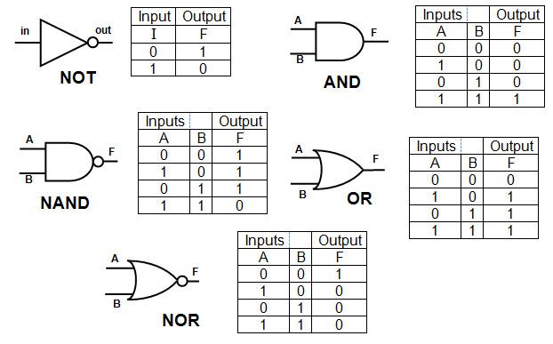
A summary of
how each circuit behaves is called a TRUTH TABLE and the circuits themselves are usually
called LOGIC GATES.
The truth tables and symbols for the most common logic gates are
shown below.
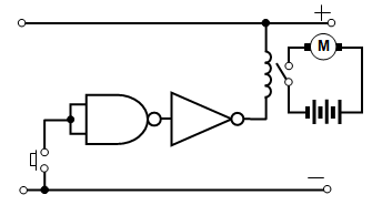
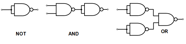
One of the most useful circuits in school electronics is the NAND gate
and so we will think about what it does in a little more detail.
(a) it has two inputs - if either
(or both) these are 0 then the output is 1 (high) , but if both are 1 the output is 0 (low)
(b) a
flying lead (unconnected input) is high (1)
(c) the output current from the NAND gate will only
be a few milliamps. It will therefore operate a buzzer with difficulty but will NOT operate a motor
(the motor will need hundreds of milliamps)
(d) you will need a driver relay module (see
later) to operate the motor from a NAND gate.
 How low does the input voltage of a NAND gate
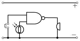
(a)
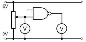
Burglar alarm
When the switch is closed one
input of the NAND gate is LOW. When the LDR is in the light the other input is LOW. This means
that if either of these things happen, i.e. the switch is closed or the light is on one of the inputs is
LOW, the output is HIGH and the buzzer sounds.
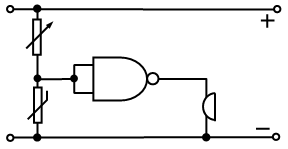 (b) Freezer warning
buzzer
(b) Freezer warning
buzzerYou will find that the
output from the NAND gate is not sufficient to run a motor, it may not even be enough to operate
a buzzer if the batteries are at all flat. (The NAND gate output current is a few milliamps while
the motor requires many hundreds of milliamps to run it)
You can overcome this
problem with the DRIVER RELAY module. This allows a small current to operate a switch that
will allow a much larger current to flow in another circuit.
The applications of the driver
include:
(a) running an electric motor
(b) reversing an electric motor
(c) switching on
a 12V 1.2W lamp for automatic light with a NAND gate