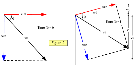
The circuit shown in Figure 1 contains both resistance and capacitance, and therefore both the
component and the frequency of the supply voltage affect the current in the circuit.
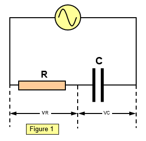
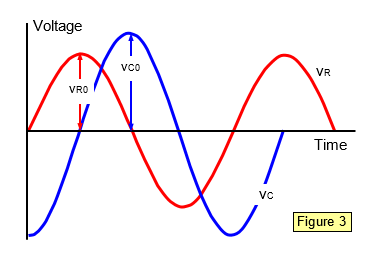
The a.c. resistance of such a circuit is known as the impedance of the circuit and is denoted by the symbol Z. Impedance is measured in ohms. We will now deduce the impedance of the circuit using the vector treatment. Consider the voltages round the circuit. The supply voltage will be denoted by Vo and the voltages across the resistor and capacitor by VR0 and VC0 respectively. We know that for a resistor the current and voltage are In phase, while for a capacitor the current leads the voltage by 90o; vR0 therefore leads vC0 by 90o, as shown in the vector diagram in Figure 2.