Kirchhoff's Rules
These two important rules apply to all electrical circuits and
are particularly helpful when dealing with branched circuits:
1. The algebraic sum of the currents at a junction is
zero. In other words there is no build up of charge at a junction
2. The sum of the
changes in potential round a closed circuit must be zero.
Rule 1 is about charge
conservation while rule 2 is about energy conservation.
We can see how these rules work
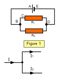
by considering the circuit shown in Figure 1.
Rule 1At the point B there is a
junction
Current flowing from the cell (I) = Current in R
1 (I
1) + current in R
2
(I
2)
Rule 2
Round loop A,B,C,D,E: p.d across cell = - p.d across
R
1 This represents a gain of potential in the cell but a loss in R
1
Round loop B,C,D,B: p.d across R
1 = - pd across R
2 In this
equation there is a minus because we are moving 'against' the current in R
2
An
example of the use of Kirchhoff's laws
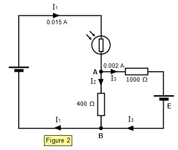
Applying Kirchhoff's first law to junction
A:
Current in the 400 Ω resistor = 0.015 ñ 0.002 =
0.013 A
Potential difference across 400 Ω
resistor = 0.013x400 = 5.2 V
This is the potential difference between A and B
via the 400 Ω resistor but it is also the potential
difference across the right hand branch of the circuit via the 1000 Ω resistor and the cell of e.m.f
E.
The potential difference across the 1000 Ω resistor is:
IR = I
3x1000 = 0.002x1000 = 2
V
Applying Kirchhoff's second law to the right hand branch and
considering an anticlockwise direction from the cell:
E.M.F of the cell
(E) = -0.002x1000 + 5.2 = -2 + 5.2 = 3.2 V
The minus sign is there
because the current in the 1000 Ω resistor is travelling in the opposite
direction to that in which the e.m.f of the cell is acting. Note that the potential difference between A and B is greater than the emf (E) of the cell.
Example problem
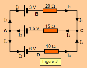
Consider the circuit shown in Figure 3.
Calculate the current shown in each resistor.
The directions of current have been chosen arbitrarily.
When we have finished the calculation it may be that
we have chosen them incorrectly.
If so we can simply reverse them on the diagram.
(a) Rule 1
Apply rule 1 to junction A
I
2 = I
1 + I
3 (1)
(b) Rule 2
(i) Choose the loop ABC
The sum of the e.m.f.s round this loop is the sum of the (IR) products in the loop.
1.5 ñ 3 = 20 I
1 + 15 I
2
Therefore: - 1.5 = 20 I
1 + 15 I
2 (2)
(ii) Now consider the loop ADC
The sum of the e.m.f.s round this loop is the sum of the (IR) products in the loop.
1.5 ñ 6 = 10 I
3 + 15 I
2
Therefore: - 4.5 = 10 I
3 + 15 I
2 (3)
Using equations 1 and 2: - 1.5 = 20 I
2 - 20
I
3 + 15 I
2 = 35 I
2 - 20 I
3 (4)
Now using equations 3 and 4: - 9 = 20 I3 + 30 I
2
Solving these gives: I
1 = 0.046 A, I
2 = - 0.162 A, I3 = - 0.208 A
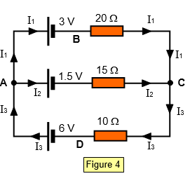
Notice that two of these currents calculated in
the example problem are negative. This means that we have chosen the wrong direction for these
currents in the original circuit.
A circuit with the currents shown in their correct directions is
shown in Figure 4.
We can check the result by
considering the loop ABCD and using the original current directions.
6 ñ 3 = 3 = 20
I1 ñ 10 I3 = 20x0.046 - 10x(-0.208) = 0.92 + 2.08 = 3
This rule is rather
like going round a helter skelter. You start at the top and travel round, going down some slopes
and up others. Similar to the consideration of the potential differences met when 'travelling' round
an electrical circuit.
Problems
1. 20 identical light bulbs are connected in series across a 240V d.c supply.
(a) what is the p.d across each bulb
(b) what is the potential at the join of the second and third bulbs from the negative terminal?
2. If two cells, one of 4.5V and the other of 3V are connected in parallel what is the p.d across the junction between them?
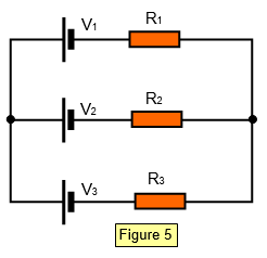
3. Calculate the currents in the three
resistors shown in Figure 5 for the values given below
(a) V
1 = 2 V V
2 = 4 V V
3 = 1.5 V
R
1 = 10 Ω R
2 = 15 ΩR
3 = 20 Ω
(b) V1 = 3 V V2 = 6 V V3 = 1.5 V
R1 = 4 Ω R2 = 8 Ω R3 = 12 Ω
(c) V1 = 6 V V2 = 3 V V3 = 1 V
R
1 = 16 Ω R
2 = 15 Ω R
3 = 8 Ω
A VERSION IN WORD IS AVAILABLE ON THE SCHOOLPHYSICS USB