
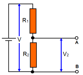
Note that the input voltage (V) in this case supplied by the battery is constant. The current flowing through
both resistors is the same (series circuit) and so the output voltage across one of them
depends simply on the two resistance values and the input voltage.
(V = IR1
+ IR2 and V2 = IR2 and so V2/V =
R2/[R1+R2])
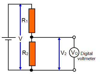
If we now
attempt to actually MEASURE the output voltage things may change.
(a) Firstly
consider using a digital voltmeter with very high (if not virtually infinite) resistance (RV). The
resistor R2 and the voltmeter are connected in parallel and so their combined
resistance (R) is given by the equation;
1/R = 1/R2 +1/RV
but as we
have said, RV is huge – almost infinite and so 1/RV is virtually 0 and can be ignored.
This means that 1/R = 1/R2 and so R = R2.
The output voltage (Vo) measured by
the meter really is that across R2, in other words V2.
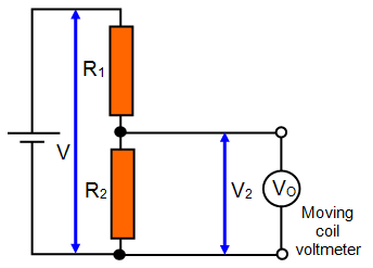 (b) A moving coil meter. These meters have a much lower resistance than a digital meter, usually
some tens of kΩ. This means that the combined resistance of R2 and RV is affected
by the resistance of the voltmeter and is actually lower than R2. (Connecting two
resistors in parallel gives a resulting resistance lower than either resistor).
(b) A moving coil meter. These meters have a much lower resistance than a digital meter, usually
some tens of kΩ. This means that the combined resistance of R2 and RV is affected
by the resistance of the voltmeter and is actually lower than R2. (Connecting two
resistors in parallel gives a resulting resistance lower than either resistor).
The
proportion of the input voltage (V) dropped across R2 therefore falls and so the
output voltage (Vo) is less than that measured with a digital
meter.
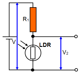
The LDR is a component that has a resistance that changes when light falls on it. As the intensity of
the light is increased so the resistance of the LDR falls.
If the LDR is connected as part
of a potential divider as shown in the diagram then as the light level is increased its
resistance falls and the proportion of the input voltage dropped across it will also
fall.
So in the light V2 is low and in the dark V2 is
high.
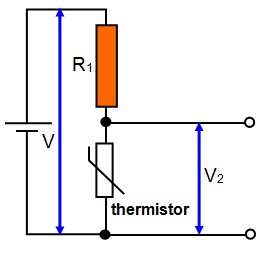
Something very similar happens if R2 is replaced by a
thermistor. As the temperature of the thermistor rises its resistance falls and so the voltage
dropped across it falls.
When the thermistor is hot V2 is low and when the
thermistor is cold V2 is high.