Resistance
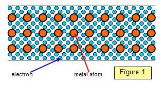
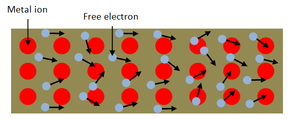
The free
electrons in a metal are in constant random motion. As they move about they collide with each
other and with the atoms of the metal. If a potential difference is now applied across the metal the
electrons tend to move towards the positive connection. As they do so their progress is interrupted
by collisions.
These collisions impede their movement and this property of the material is called its
resistance. If the temperature of the metal is raised the atoms vibrate more strongly and the
electrons make more violent collisions with them and so the resistance of the metal increase (see
later).
The resistance of any conducting material depends on the following factors:
(a) the material itself (actually how many free electrons there are per metre cubed)
(b) its
length
(c) its cross-sectional area and (d) its temperature
The resistance of a given
piece of material is connected to the current flowing through it and the potential difference between
its ends by the equation:
Resistance (R) = Potential Difference (V)/ Current (I)
The units of resistance are ohms (Ω).
A specimen has a resistance of 1 Ω if a current of 1A flows through it when a potential difference of 1 V is applied between its ends.
Example problem
Calculate the resistance of a specimen if a current of 0.5 mA flows in it when a voltage of 6 V is applied across it.
Resistance = V/I = 6/0.0005 = 1.2x10⁴ Ω = 12 kΩ
Student investigation
Use a sample of conducting putty to find out how the resistance of a given volume of the putty depends on:
(a) its length (b) its cross-sectional area
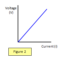
Ohm's Law
If the ratio of p.d to current remains constant for a
series of different p.d.s the material is said to obey Ohm's Law. This is true for a metallic conductor
at a constant temperature (see Figure 2)
This means that although we can always work
out the resistance of a specimen knowing the current through it and the p.d across it. However if
these quantities are altered we can only PREDICT how it will behave under these new conditions if
it obeys Ohm's law.
It is also vital to realise that the resistance is simply the ratio of the voltage
and current at a particular point and NOT generally the gradient of the VI curve.
It is important
to realise that Ohm's Law only holds for a metallic conductor if the temperature is constant.
Ohm’s Law:
The ratio of the potential difference (V) across a metallic conductor to the current (I) flowing through it is constant at a constant temperature.
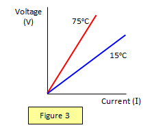
This means that if the temperature of the metal is held steady at
say 15o C the variation of current and voltage will be linear. However if the temperature of the
metal changes (as in the filament of a light bulb) then the resistance will also change. The
collisions between the electrons and the atoms will occur more often and be more violent.
So if the wire is raised to 75o C a second set of readings can be taken – they will still be
linear but the resistance of the wire (the ratio of V to I) will be greater (see Figure 3).
It is worth having a look at two graphs that show how the resistance of two types of
material change when their temperature is changed.
The first is a metal wire (Figure 4(a)), and the second is a (negative temperature coefficient) thermistor (Figure 4 (b).
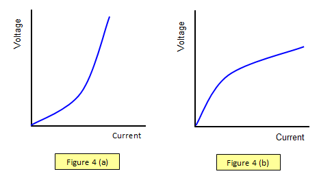
In the case of the metal wire the
resistance increases as the temperature increases, you can see this because the ration of pairs of
points on the V-I graph increases at high currents (hot wires). In the case of the thermistor the
resistance decreases as the temperature increases, you can see because the ratio of pairs of
points on the V-I graph decreases at high currents (high temperatures.).
Although the gradients of the graphs suggests a change in resistance do not be tempted to use the gradient to
work out the resistance, you must still deal with the voltage/current ratio only.
The reason
that the thermistor decreases is because the thermistor is a semiconductor and more free
electrons are produced as the temperature is raised.
(In fact more electrons are raised to
the conduction band of the material.)
Electron theory of resistance
We can consider
the electrons in a solid to have a random motion similar to a cloud of gas molecules.
An
electric field of intensity F is placed across a length L of the conductor. Let the conductor be of
resistivity
r and resistance R, and have n conduction electrons per unit volume.
The electric
field (E) across the conductor is given by E = V/L and therefore Ee = Ve/L = F
where F is
the force on the electron.
Using Newton's second law of motion the acceleration of an
electron due to this field is then given by:
acceleration = Ve/mL
where m is the
electron mass.
If the time between electron collisions is t, then (Figure 5) the velocity v' just
before a collision is
v' = Vet /Lm
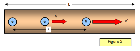
The average velocity between collisions is therefore Vet = v, but since I = nAve we have:
I = e
2tnAV/2Lm
and this gives for the resistance:
Resistance (R) = V/I =2Lm /e2tnA
If we consider the thermal velocity of the electrons to be around 10
6 ms
-1 then the time between collisions in copper is 5x10
-14 s and
the distance travelled is some 5x10
-8 m, much greater than the interatomic spacing which is about
2 x 10
-10m.
See also:
Resistivity
and:
Series and parallel resistors
A VERSION IN WORD IS AVAILABLE ON THE SCHOOLPHYSICS USB