This device, which is the basis of many ignition systems for cars,
uses the mutual inductance between two coils to produce a high voltage. A simplified diagram of an
induction coil is shown in Figure 1.
A primary coil consisting of a small number of turns of thick
copper wire is wound round a bundle of soft iron rods that are insulated from each other. The
secondary coil, which may consist of many hundreds of metres of fine wire, is wound over the primary.
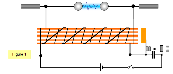
On closing the switch a current flows in the
primary and magnetises the core, which attracts the armature and breaks the circuit. The magnetic
field dies away; the armature is pulled back by the spring and the current flows again. The process
then repeats itself.
The rapidly changing magnetic field produces a high voltage in the primary
coil; the greater the rate at which this field changes, the greater is the induced voltage. A capacitor is
connected across the make and break contacts; this reduces sparking and also causes the field to die
away much more rapidly than if the capacitor had not been present. As a result the induced voltage in
the secondary is much greater when the circuit is broken than when it is made. The secondary current
therefore pulsates, but it is always in the same direction. Sparks of several centimetres in length may
be obtained through air at atmospheric pressure with quite small induction coils, and larger coils were
originally used to power X-ray tubes.
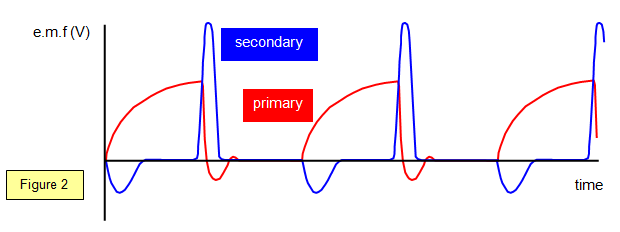
Figure 2 shows how the primary and secondary voltages
produced by the induction coil vary with time. Note the rapid decrease of primary voltage at the break
and the corresponding high value of the e.rn.f. induced in the secondary.