
The electric motor is a device that converts electrical energy into rotational kinetic energy by the action of the force on a coil pivoted in a magnetic field. It differs from the moving coil meter in that the coil is free to rotate. In practical motors there are usually more than one coil to improve the performance and give a more constant torque. A cylindrical laminated iron core provides inertia and a radial field.
A coil in a magnetic field experiences an equal but opposite force on its two
sides and so the coil twists.
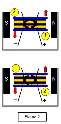
If we start with the coil in the position shown in diagram
Figure 2(a) then there will be an upward force on side (1) of the coil and a downward force on
side (2) of the coil. The coil will therefore start to twist in an anticlockwise direction.
The
inertia of the coil and core keeps it turning until the input wires make contact with the ends of the
coil again. This time the positive wire touches side (2) and the negative wire touches side (1).
(Figure 2(b)).
Side (2) now moves up and side (1) moves down — the coil continues to turn
in an anticlockwise direction. This process then continues and so the coil spins.
The
d.c motor consists of:
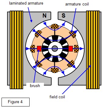
(a) a number of coils of fine wire wound on
(b) a laminated soft
iron armature
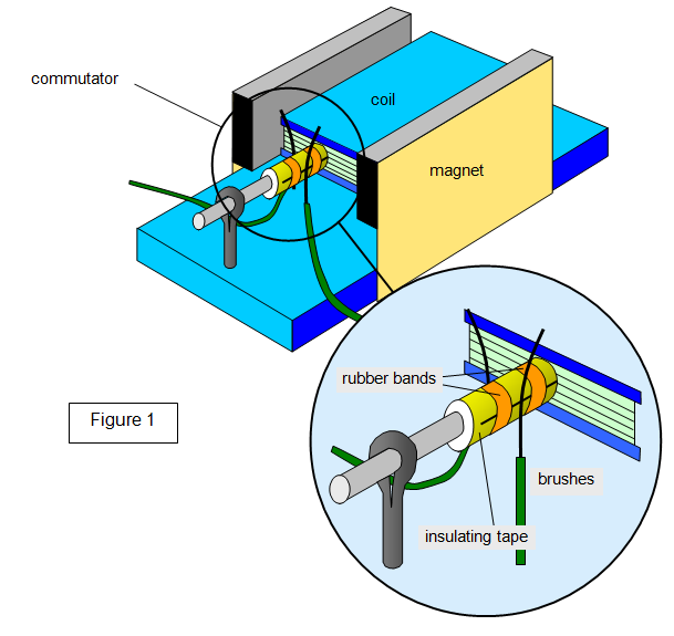
(c) a set of brushes to allow current to enter and leave the windings;
(d) a
commutator to reverse the current in the coils;
(e) a set of external field
coils.
A current flows round the coil and one side is forced up by the magnetic field and the other is forced down Figure 3(b). The motion is made continuous by reversing the current direction through the coil by means of a split ring commutator and two brushes (Figure 3(c) and (d). The coil is kept rotating during the short time interval when there is no force acting on it by its own inertia.

By having a set of coils instead of the single armature coil, the time when
the armature 'freewheels' is reduced and the number of 'kicks' per rotation greatly increased.
This makes the torque applied by the motor very nearly constant.
The distance between the field
coils and the armature is made as small as possible by using magnets with curved pole pieces to
increase the flux density, and the armature core is laminated to reduce eddy current
losses.
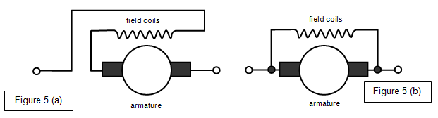
In
series-wound motors, the current varies considerably with the load and speed control is difficult,
but the starting torque is large. This type of motor is therefore used for cranes and winches and
for high-speed motors such as those used in fans and grinding wheels where speed control is
not important.
In shunt-wound motors, the speed vanes little with the load and it can be
easily controlled; however, the starting torque is not as great as that of a series-wound motor.
Shunt-wound motors are used in machines where the speed is important, such as record players
and machine tools.