Force on a current in a magnetic field
The strength of a magnetic field is
usually measured in terms of a quantity called the magnetic flux density of the field, B. A
definition of B requires a consideration of the forces produced by electromagnetic
fields.
When a wire carrying a current is placed in a magnetic field the
wire experiences a force due to the interaction between the field and the moving charges in the
wire. A very good demonstration is the so-called catapult field experiment in which a wire
carrying a d.c. current can be made to move in the field of two flat magnets. (See Figures 1-3).
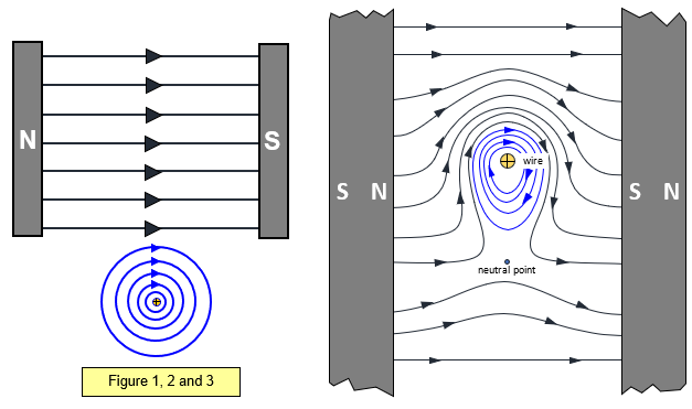
The fields of the wire, the
magnets and the combined fields are shown in Figures 1,2 and 3. Notice that the wire moves
away from the area of highest field intensity (where the magnetic field lines are closest) to a
region lower intensity.
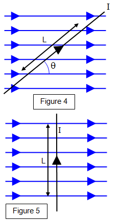
The force F on the wire in Figure 4 can be shown to be proportional to
(a) the current on the wire I,
(b)
the length of the conductor in the field L,
(c) the sine of the angle θ that the conductor makes
with the field , and
(d) the strength of the field - this is measured by a quantity known as
the magnetic flux density B of the field. The force is given by the equation:
Force on current in magnetic field:
F = BIL sin θ
The units for B are tesla
(T).
The special case is when the wire is at right angles to the field (that is θ = 90
o). This gives the greatest force on the wire. (See Figure 5)
The flux density of a field of one tesla is therefore defined as the force per unit length on a wire carrying a current of one ampere at right angles to the field.
Example problem
Calculate the force on a power cable of length 200 m carrying a current of 200 A in a direction N 300E at a place where the horizontal component of the Earth's magnetic field is 10-5 T.
The wire will experience an upward force given by F = BIL sin = 10-5x200x200x0.866 = 0.35 N
Fleming's left-
hand rule gives the direction of motion for the case when field and current are at right angles
(see diagrams below).
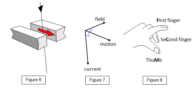
The
First finger represents the
Field direction (N to S), the se
Cond finger
the
Current direction (positive to negative) and the thu
Mb the direction of
Motion.
For a large permanent magnet of the type used in schools the flux
density between the poles is about 1 T, magnadur magnets have a flux density of some 0.08 T
close to their poles and the horizontal component of the Earth's magnetic field is about
10
-5 T.
Having defined B we can express the magnetic flux passing through a
surface as BA where A is the area of the surface at right angles to the field. Magnetic flux (φ) is measured in webers (Wb).
Magnetic flux (φ) = Magnetic flux density (B) x Area (A)
A VERSION IN WORD IS AVAILABLE ON THE SCHOOLPHYSICS USB