Capacitor networks
In practical circuits capacitors are often joined
together. We will consider the cases of two capacitors, first in parallel and then in
series.
(a) Capacitors in parallelConsider two
capacitors connected in parallel as shown in Figure 1
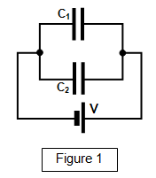
The potential across both capacitors is the same (V) and let the
charges on the capacitors be Q1 and Q
2 respectively.
Now Q = CV, and so Q =
C
1V and Q = C
2V. But the total charge stored Q = Q
1 + Q
2,
therefore
Q = Q
1 + Q
2 = V(C
1 +
C
2)
Giving:
Capacitors in parallel:
C = C1 + C2
where C is the capacitance of the
combination.
(b) Capacitors in seriesIn this case the
capacitors are connected as shown in Figure 2.
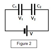
The charge stored by each capacitor is the same. If
V
1 and V
2 are the potentials across C
1 and C
2 respectively
then:
V
1 = Q/C
1 and V
2 = Q/C
2. Therefore:
V = V
1 + V
2 = Q(1/C
1 +
1/C
2)
Hence:
Capacitors in series:
1/C = 1/C1 + 1/C2
where C is the capacitance of the
combination.
(Notice that they are the "reverse" of the formulae for two resistors in series
and parallel)
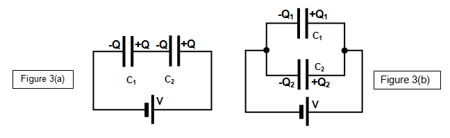
The charge distribution on series and parallel
capacitors
When two capacitors are joined tighter in a circuit and then connected to
a voltage supply charge will move onto the plates. The actual distribution of charge for a
series and parallel circuit is shown in Figure 3(a) and (b).
Joining two charged capacitors
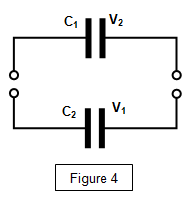
If two capacitors are joined together as shown in Figure 4
then:
(a) there is no change in the total charge stored by the system;
(b) the potential
across the two capacitors becomes equal
(c) the combined capacitance of the two
capacitors in parallel becomes
C = C1 + C2There is usually
a loss in energy when the two capacitors are joined; this is because unless the potential
differences across them are equal, charge will flow to equalise this difference.
The flow
of charge results in heating in the connecting wires and a consequent loss of energy.
Breakdown potential for a capacitor
Every capacitor has a working
voltage, this is the maximum potential that should be applied between the plates. Any more
than this and the dielectric material between the plates will break down and become
conducting and the capacitor will be destroyed, usually resulting in a small bang as the
material breaks down.
Example problems
1. Calculate the capacitance of the capacitor formed by joining:
(a) two 100 μF capacitors in series
(b) two 100 μF capacitors in series
(a) 1/C = 1/C1 + 1/C2 = 2/100x10-6 = 20 000 Therefore C = 50 μF
(b) C = C1 + C2 = 100x10-6 + 100x10-6 = 200 μF
2. 250 μF capacitors are joined in series to a 12V supply.
Calculate:
(a) the potential difference across each capacitor
(b) the charge on each plate of each capacitor
(a) since the capacitors are equal the potential across each will be the same and equal to 6V
(b) for each capacitor C = Q/V therefore Q = CV = 250x10-6x12 = 3x10⁻³ C = 3 mC
Capacitance formulae
The formulae
for capacitors of some other common shapes are given below, although the proofs of these
formulae are not needed at this level.
| Sphere (radius a) |
4πεa |
| Concentric spheres (radii a and b) |
4πεab/[b-a] |
| Concentric cylinders (radii a,b,length L) |
2πεL/[ln(b/a)] |
| Two long, parallel wires
(separation d,radius a,length L (d >> a)
|
εL/ln[d/a] |
| Parallel-plate capacitor of area A containing a thickness x of dielectric and thickness b of air |
εA/(εrb + x) |
A VERSION IN WORD IS AVAILABLE ON THE SCHOOLPHYSICS CD