LOGIC GATES
The switching action of a transistor makes it especially
suitable for use in digital logic circuits where the output is either 0 or 1 depending on the input.
Applications of such circuits are to:
Switch on a water pump on a hot sunny day
Sound an alarm if the pilot light of a boiler went off
Sound an alarm if a burglar stepped on a pressure pad or shone his torch
Switch a light on if it was a cloudy day
Add two simple binary numbers together
Switch on a fan if a darkroom door was shut and it was warm inside
All these things and indeed many more can be done with ELECTRONIC LOGIC CIRCUITS. These circuits are ones that can make decisions.
Different decisions need different circuits.
If you refer to the switching circuit for the transistor
you will see that the output voltage is high (consider this as 1) when the input voltage is low
(consider this as 0). This is the basic NOT gate - there is an output when there is not
an input.
Combinations of these switching circuits can be made into logic gates that will
perform simple decisions within a microprocessor. These logic gates are the basis of all
decisions within computers and from now on we will consider their effects rather then their
internal structure.
We will consider the following types of logic gate:
(a) NOT gate - this gives
an output 1 for an input of 0
(b) NOR gate - this gives an output 1 for neither of two inputs
1
(c) OR gate - this gives an output 1 for either of two inputs 1 and both inputs 1
(d) AND
gate - this gives an output 1 for both two inputs 1
(e) NAND gate - this gives an output I for
either but not both of two inputs 1 or both inputs 0
(f) EXCLUSIVE-OR - this gives an output I
for either but not both of two inputs 1
(g) EXCLUSIVE-NOR - this gives an output 1 when
both inputs are 0 or 1
Because of its wide use in modern digital electronics the NAND
gate will be considered as a basic building block for a variety of logic circuits. In fact a number of
other logic gates can be constructed from NAND gates as is shown below. The circuit in Figure 1
shows how a NAND gate might be constructed from discrete components, although it would
normally be in the form of an integrated circuit.
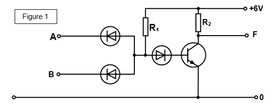
There will be a large output voltage across the transistor as long
as at least one of the inputs is made low.
Think about just two of the
examples:
The hot sunny dayTo switch on the pump it must be hot AND sunny.
This needs an AND circuit.
The burglar alarmTo sound the alarm the burglar has
to step on the pressure pad OR switch on his torch. This needs an OR circuit.
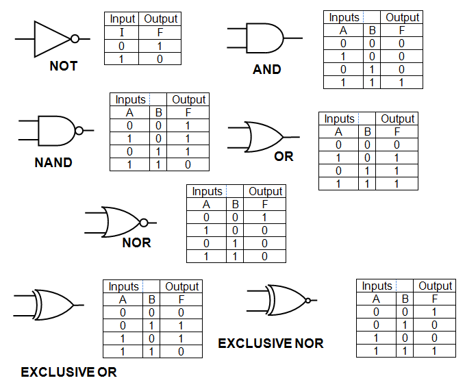
A
summary of how each circuit behaves is called a
TRUTH TABLE and the circuits themselves are
usually called
LOGIC GATES. The truth tables and symbols for the most common logic
gates are shown below.
SUMMARY OF THE USE OF THE NAND GATE
One of the most useful circuits in school
electronics is the NAND gate and so we will think about what it does in a little more
detail.
(a) it has two inputs - if either (or both) these are 0 then the output is 1 (high) , but if
both are 1 the output is 0 (low)
(b) a flying lead (unconnected input) is high (1)
a few
milliamps. It will therefore operate a buzzer with difficulty but will NOT operate a motor (the
motor will need hundreds of milliamps)
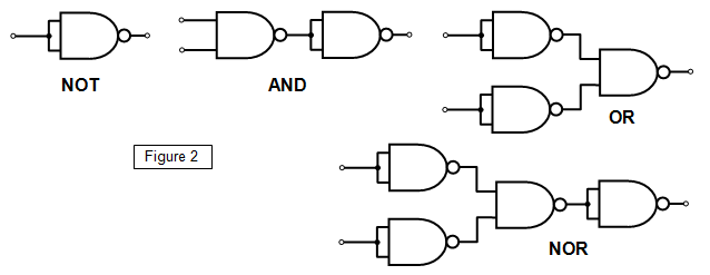
MAKING OTHER LOGIC GATES FROM NAND
GATES
The circuits below show you how to make a NOT, OR, NOR and AND gate using
NAND gates.
Student investigation
Design and construct circuits using NAND gates that will do the following things:
(a) switch a light on when it gets dark
(b) switch a light on when it gets light
(c) detect when an object is longer than a certain length
(d) switch on a warning light when either of the two front doors of a car are open
(e) sound a buzzer if there is a person sitting on the front seat of a car and the ignition key is turned
(f) sound a buzzer when all three coconuts on a coconut shie have been knocked off
(g) switch a light on if a safe door has been closed but not locked
(h) switch on a buzzer when the temperature of a room falls below a certain value