
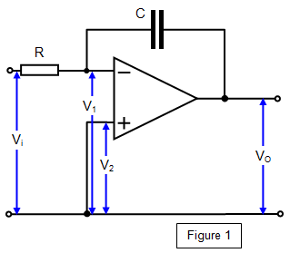
If the feedback resistor of the inverting voltage amplifier is
replaced by a capacitor, as shown in Figure 1, a ramp generator or integrator is formed.
If the
input voltage V1 is constant and RC = 1 s, then the output voltage Vo after a time t is given by Vo
= Vit
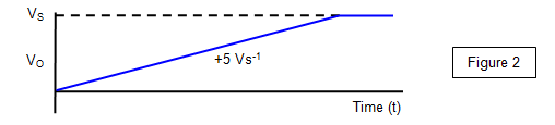
This means that the output voltage
rises steadily with time (hence the name of ramp generator). This increase continues until the op amp
saturates at a voltage just less than the supply voltage.
The variation of the voltage output
against time is shown in Figure 2 (this shows a rate rise of potential difference of 5 Vs-1). Since P is
almost zero (a virtual earth) the voltage across the input resistor R will be the input voltage V1 and the
voltage across the capacitor C will be the output voltage Vo. If we assume that no current flows into the
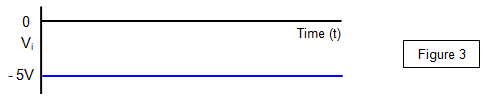
inverting input of the op amp, then all the input current I flows to the capacitor C and so charges it up.
If V1 is constant then I will be constant
(see Figure 3), and its value will be given by I = Vi/R
C therefore charges at a constant rate.
If Q is the charge on C at a time t and if the
potential difference across it changes from 0 to Vo in that time, then (since I is constant) Q = VoC = It
Therefore combining this with the equation above gives: -VoC = Vit/R or - Vo =
[1/RC]Vit
If C and R are chosen such that CR = 1 then:
This last equation is the reason why this circuit is also known as an integrator, since the value of V1 is integrated over a certain time interval. This type of circuit will be found in most oscilloscopes as a means of producing the steadily rising voltage needed for the time base. The ramp generator is also used in the digital voltmeter, the analogue to digital converter and in digital recording.