Rectification using a diode
The diode can be used as a simple rectifier
because of the difference in its forward and reverse bias properties.
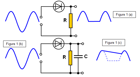
The effect of a
single diode on an a.c. voltage is shown in Figure 1(a) and 1(b); this is known as half-wave
rectification. The addition of a capacitor will produce a smoothing effect on the output, as
shown in Figure 1(c).
Bridge rectifier circuit
Full-wave
rectification may be obtained using the bridge rectifier circuit. This is basically four diodes
connected in a square (Figure 2) and once again the smoothing effect of a capacitor is
shown.
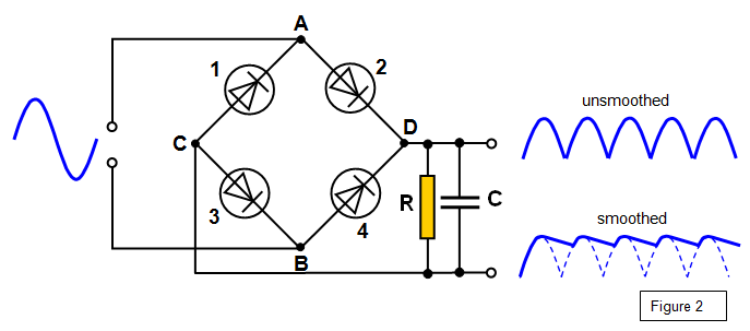
The action of the
bridge rectifier can be explained as follows. If point A is positive diode 2 conducts, making D
positive. If point B is positive diode 4 conducts, still keeping D positive.
A VERSION IN WORD IS AVAILABLE ON THE SCHOOLPHYSICS CD