Boolean algebra
In 1847 George Boole devised a simple method of
analysing logic circuits, over a century before the first integrated circuit had been produced.
Boolean algebra, as this branch of mathematics is called, operates with the following
rules.
(Note: We will use A'' to represent A double
overscore)
If A is the input to a circuit and the notation A' means NOT A then:
1. A +
0 = A
2. A+1 = 1
3. A.0 = 0
4. A.1 = A
5. A'' = A
6. A.A = A
7 A.
A
= 0
8 A+
A = 1
9. A + A = A
Using this notation we can write down the
outputs from the logic gates that we have considered.
OR output = A + B
AND
output = A.B
NOT output =
ANAND output =
[A.B]NOR output =
[A+B]Now we can handle expressions in Boolean algebra in exactly the same way as
normal algebra; however, the results will not mean the same as in normal algebra. For
example:
A.(B + C) = A.B + A.C
but if we now give A, B and C values with A
=1, B = 1, C = 0 then the final result using the rules above is:
1+0 = 1
We can
apply these rules to the slightly more complex circuit in Figure 1.
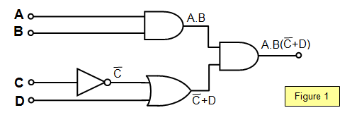
The final output is A.B(
C+ D) and this can be multiplied
out to give A.B.
C + A.B.D
Using the values A = 1, B = 1, C = 0, D = 1 gives:
A.B.C +
A.B.D = 1 + 1 = 1 and so the output of the circuit is 1
A VERSION IN WORD IS AVAILABLE ON THE SCHOOLPHYSICS USB