Knowledge of the focal length of a lens is vital in the construction of all optical instruments, from spectacles to large astronomical telescopes. The range of possible focal lengths is very large, from a few milli- metres for the objective lens of a microscope to 20 m in a large telescope. Several simple methods are described because they all illustrate different aspects of the lens formula.
(i) The focusing method
 A rough guide
to the focal length of a lens can be obtained by focusing light from a distant object, such as
the Sun, on to a screen.
A rough guide
to the focal length of a lens can be obtained by focusing light from a distant object, such as
the Sun, on to a screen.
(ii) The graphical method
A graph of 1/u against 1/v
can be plotted and the focal length (f) found from this. The point where the line intersects
either axis is 1/f.
 (iii)
(iii) The
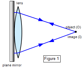
plane mirror method
The lens is placed on the mirror as shown in Figure 1, and the
object is moved until object and image coincide. This point is the principal focus, since light
from it will emerge parallel from the lens and so be reflected back along its original path
when it strikes the mirror. The object can be either a pin or a point source.
Since R
= 2f for a lens of glass of refractive index 1.5 placed in air, the value of f can be
found.
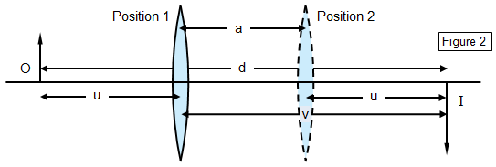
For a given
separation of the object and screen it will be found that there are two positions where a
clearly focused image can be formed (Figure 2). By the principle or reversibility these must
be symmetrical between 0 and I.
Using the notation shown: d = u+v
and a = v ñ u
Therefore: u = [d ñ a]/2 and v = [d +
a]/2
Substituting in the lens equation gives:
2/[d ñ a] + 2/[d + a] = 1/f and
hence f = [d2 ñ a2]/4d
(v) The minimum distance
method
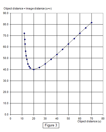
This more mathematical method derives from the fact that there is a minimum
separation for object and image for a given lens. This can be shown if u + v is plotted against
either u or v. A minimum is formed (shown by Figure 3) and this can be shown to occur at
the point where u = v = 2f and u + v = 4f, that is, the minimum separation for object and
image is 4f.
So far all the methods have been for convex
lenses where a real image can be produced. We will now consider some methods for
concave lenses.
(i) An auxiliary convex lens is used, in contact with the concave
lens. It must be of greater power than the concave lens with one of its faces having the
same radius of curvature as one of the faces of the concave lens. The focal length of the
combination is then given by
1/F = 1/f + 1/f'
where the focal length of the convex
lens f' can be found by the methods described above.
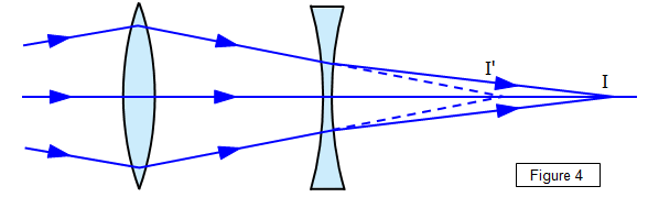
(ii) A convex lens of greater
power is used to give a virtual object for the concave lens (Figure 4).