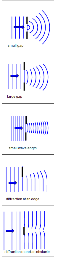
When
a wave hits an obstacle it does not simply go straight past, it bends round the obstacle. The
same type of effect occurs at a hole - the waves spread out the other side of the hole. This
phenomenon is known as diffraction and examples of the
diffraction of plane waves are shown in Figure 1.
The effects of diffraction are much more noticeable if the size of the obstacle is small (a few wavelengths
across), while a given size of obstacle will diffract a wave of long wavelength more than a
shorter one.
Diffraction can be easily demonstrated with sound waves or microwaves. It
is quite easy to hear a sound even if there is an obstacle in the direct line between the source
and your ears. By using the 2.8 cm microwave apparatus owned by many schools very good
diffraction effects may be observed with obstacles a few centimetres across.
The coloured
rings round a street light in frosty weather, the coloured bands viewed by reflection from a
record and the spreading of light round your eyelashes are all diffraction effects. Looking
through the material of a stretched pair of tights at a small torch bulb will also show very good
diffraction. A laser will also show good diffraction effects over large distances because of the
coherence of laser light.
Diffraction is essentially the effect of removing some of
the information from a wave front; the new wave front will be altered by the obstacle or aperture.
Huygens' theory explained this satisfactorily.
Grimaldi first recorded the diffraction of
light in 1665 but the real credit for its scientific study must go to Fresnel, Poisson and Arago,
working in the late eighteenth and early nineteenth centuries.
We can define two
distinct types of diffraction:
(a) Fresnel diffraction is produced when light from a point source
meets an obstacle, the waves are spherical and the pattern observed is a fringed image of the
object.
(b) Fraunhofer diffraction occurs with plane wave-fronts with the object effectively at
infinity. The pattern is in a particular direction and is a fringed image of the
source.
Fresnel diffraction can be observed with the
minimum of apparatus but the mathematics are complex. We will therefore only treat it
experimentally here.
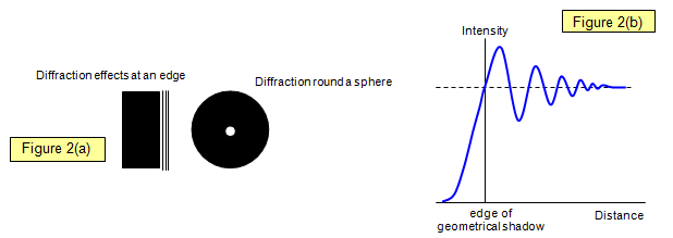
If a razor blade is placed between the observer and a point source
of monochromatic light, dark and bright diffraction fringes can be seen in the edges of the
shadow. The same effects can be produced with a pinhead, when a spot of light will be seen in
the centre of the shadow.
Fresnel was unhappy about Newton's explanation of
diffraction in terms of the attraction of the light particles by the particles of the solid, because
diffraction was found to be independent of the density of the obstacle: a spider's web, for
example, gave the same diffraction pattern as a platinum wire of the same thickness. The
prediction and subsequent discovery of a bright spot within the centre of the shadow of a small
steel ball was final proof that light was indeed a wave motion.