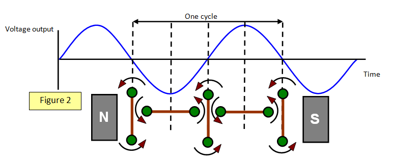
The output of the ac. generator is shown in
Figure 2. As one side of the coil cuts down through the field, the output from that side will
be positive and as it goes up it will be negative; an ac. output is produced.
The
maximum output voltage will be when the coil is parallel to the field, and is also shown in
Figure 2. This happens because the coil is cutting the field lines at the greatest rate at this
point.
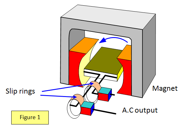
The d.c.
generator is similar to the ac. version but there are one or two important differences (See
Figure 3).
There is still a coil that rotates between the poles of a magnet but this time
the two ends of the coil are connected to a split ring — a half circle of metal that is in
contact with the stationary brushes.
If you look at the diagram you can see how this
arrangement will produce d.c.
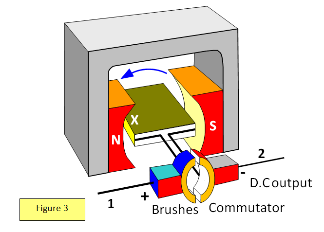
As the coil rotates the side of it that is cutting
downwards through the field (marked X on the diagram) is always in contact with brush 1.
That means that brush 1 is always positive. In the same way the side of the coil that is
going up is in contact with brush 2. The device that ensures that the two brushes
always have the same polarity is called a COMMUTATOR.
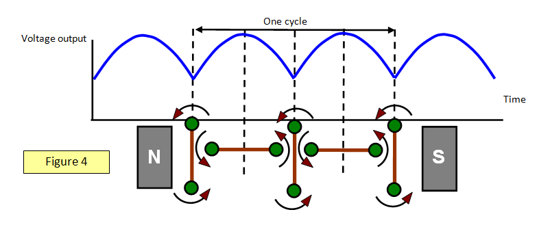
The output of the
d.c. generator is shown in the Figure 4. The output is not steady but is always in the same
direction. As with the ac. generator the maximum output voltage occurs when the coil
is horizontal and is cutting the field at right angles and at maximum
rate.