
An electric current will produce a magnetic field, a fact discovered by Oersted in 1820. The intensity and shape of this field depends on the strength of the current and the arrangement of the wires carrying it. In 1820 Sturgeon also showed that the strength of the field in a coil could be increased considerably by placing an iron core in the coil.
Magnetic fields have a large number of uses in the
modern world in, for instance, particle accelerators, plasma bottles, lifting magnets, linear
induction motors, tape recording heads and many other applications. Knowledge of those fields
has also helped in the studies of the Physics of the van Allen radiation belts, quasars and
aurorae.
You will have seen some magnetic field arrangements in your foundation level
course and we will be considering these and other field arrangements in detail.The shapes
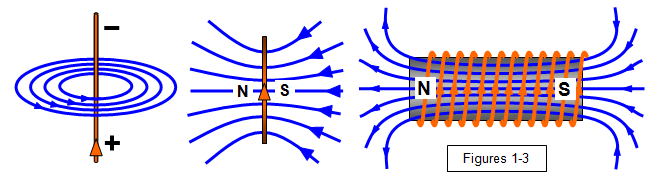
of the magnetic fields for some simple arrangements are shown in Figure 1-3. You can see that
these fields are not uniform and it is found that the strength of the field depends on the
closeness of the lines of magnetic flux.
The direction of the magnetic force can be found by
Maxwell's corkscrew rule. If we imagine ourselves driving a corkscrew in the direction of the
current, then the direction of rotation of the corkscrew is the direction of the lines of
force.
The polarity of a coil of wire can be found by Fleming's right-hand grip rule, where the
fingers of the right hand indicate the current direction and the thumb the north pole of the
solenoid.
A single wire connected to a cell and doubled back on itself has no net magnetic
field - the field produced by the current in one direction cancels that produced by the current in
the other. This is known as non-inductive winding; it is used in resistance boxes, and in the
platinum resistance thermometer.
 Student investigation
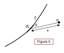
Consider a wire carrying a current I (Figure 5). The
flux density B at a point P due to a length of wire dL is given by:
dB = μoIdLsinθ/4μx2
This is known as the Biot-Savart rule, after two French physicists. The constant of
proportionality in this formula is known as the permeability of the medium and is denoted by μ.
The unit of permeability is the henry per metre (H m-1).
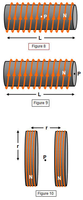 (c) At the centre of a long solenoid of n turns per metre carrying