
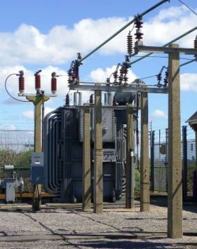
The transformer is a vital part of the National Grid
that distributes electrical energy around the country.
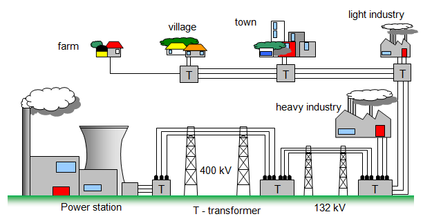
Electrical energy is generated in power
stations by generators at a potential of 25 kV. It is first stepped up to 400 kV by a transformer and then
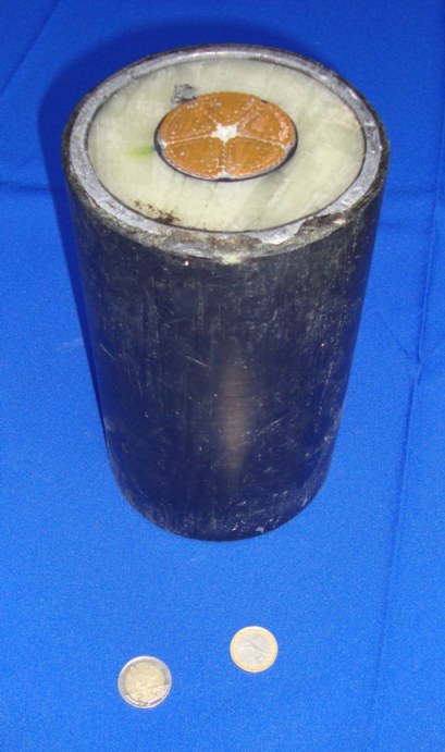
transmitted across the country in aluminium cables roughly 2 cm in diameter.
High voltages are
used because the power loss per kilometre (I2R) for a given power output will be much less at high
voltage and low current than at low voltage and high current. Despite this, even after the current has
been reduced many transmission lines carry up to 2500 A! (What must the current output from the
generators be in these cases?)
In Britain the grid system can meet a simultaneous demand of
56 000 MW supplied through some 8000 km of high-voltage transmission line. Alternating current is
used in the National Grid, although this has not always been the case, because it may be transformed
to high voltage.
Your teacher may have demonstrated a model power line arrangement using two 12V bulbs. The voltage is stepped up using a transformer from 12V to 240V. It shows clearly the energy loss in the 'power lines' between one bulb near the 'power station' end and ther other bulb at the 'consumer' end.

Under no circumstances should you attempt to repeat this experiment. It should oonly be carried out by a suitably qualified teacher in the laboratory using the commercially available apparatus.