
When two groups of waves (called wave trains) meet and
overlap they interfere with each other. The resulting amplitude will depend on the amplitudes of
both the waves at that point.
If the crest of one wave meets the crest of the other the
waves are said to be in phase and the resulting intensity will be large. This is known as
constructive interference. If the crest of one wave meets
the trough of the other (and the waves are of equal amplitude) they are said to be out of phase
by p then the resulting intensity will be zero. This is known as
destructive interference.
This phase difference
may be produced by allowing the two sets of waves to travel different distances - this difference
in distance of travel is called the path difference
There will be many intermediate conditions between these two extremes
that will give a small variation in intensity but we will confine ourselves to total constructive or
total destructive interference for the moment.
The diagrams in Figure 1 below show two
waves of equal amplitudes with different phase and path differences between them. The first
pair have a path difference of a whole number of wavelengths, including zero. The second pair have a phase difference of p or 180o and a path
difference of an odd number of half-wavelengths.
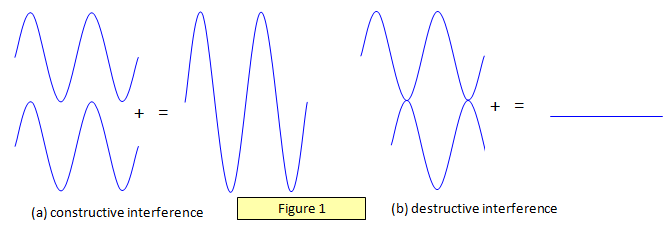
Figure 1(a) shows destructive
interference and Figure 1(b) constructive interference.
To obtain a static interference
pattern at a point (that is, one that is constant with time) we must have:
(a) two sources of
the same wavelength, and
(b) two sources which have a constant phase difference
between them.
Sources with synchronised phase changes between them are called
coherent sources and those with random phase changes are called incoherent
sources.
This condition is met by two speakers connected to a signal generator
because the sound waves that they emit are continuous – there are no breaks in the waves.
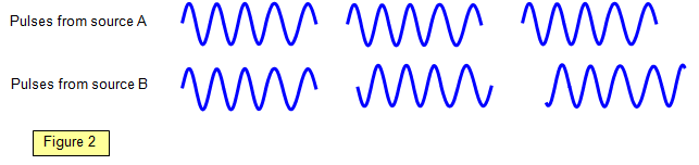
However two separate light sources cannot be used as sources for a static
interference pattern because although they may be monochromatic the light from them is
emitted in a random series of pulses of around 10-8 s duration. The phase difference that may
exist between one pair of pulses emitted from the source may well be quite different from that
between the next pair of pulses (Figure 2).
Therefore although an interference pattern still occurs, it
changes so rapidly that you get the impression of uniform illumination. Another problem is that
the atoms emitting the light may collide with each other so producing phase changes within one
individual photon. We must therefore use one light source and split the waves from it into two in
some way.
There are two ways of doing this:
(a) division of amplitude, where the
amplitude at all points along the wavefront is divided between the two secondary waves,
and
(b) division of wavefront, where the original wave-front is divided in two, half of it
forming each of the secondary waves.
However, the length of each pulse limits the path
difference that we may obtain between even these two waves from the same source. Since the
pulses are only about 10-8 s long the maximum path difference is 3 m, although in practice good
results are only obtained with shorter path differences than this.
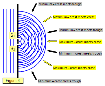
The diagrams in Figure 3-7 show two
sources S1 and S2 emitting waves - they could be light, sound or microwaves.
The plan
view of the waves in Figure 3 shows waves coming from two slits and interfering with each
other. The lines along which the path differences will give maxima or minima.
This type
of arrangement is like that produced in a ripple tank or in the double slits experiment with light
(see later).
It should be realised that between the maxima and minima the intensity will change
gradually from one extreme to the other.
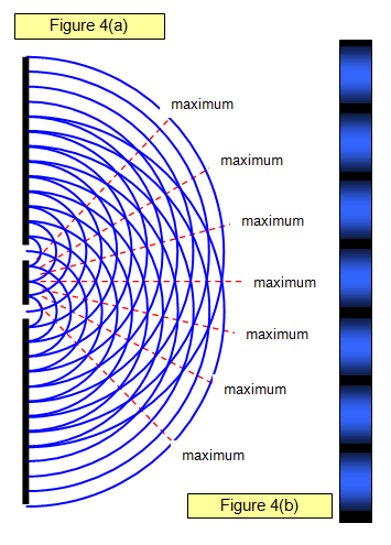
Figure 4(a) shows light interfering as it passes
through two slits. In Figure 4(b) the appearance of the interference pattern on a screen placed in the path
of the beam is shown.
You can see the maxima and minima and the way in which the
intensity changes from one to the other.

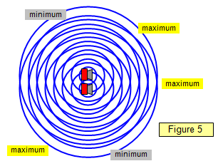
Figure 5 shows the interference effects of two speakers. The sound waves spread
out all round the speakers and a static interference pattern is formed. (Not all the maxima and minima are
labelled).
You can hear this by setting up two speakers in the lab connected to one signal generator and
then simply walking round the room. You will hear the sound go from loud to soft as you pass from
maximum to minimum. (A frequency of around 400 Hz is suitable).
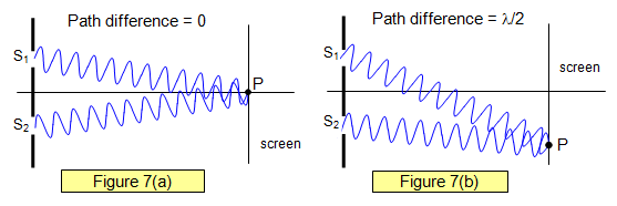
In Figures 6 and 7
you can see that at the different points on the screen the waves from S1 have travelled a different
distance from those from S2. In Figure 6 the path difference is zero, in Figure 7 it is half a
wavelength.
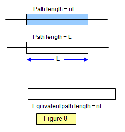
When light passes through a material of
refractive index n it is slowed down, its velocity in the material being 1/n times that in a vacuum.
For example, the velocity of light in glass is about 2.0x10⁸ ms-1 compared with about 3.00x10⁸ ms-1 in a vacuum.
The time light takes to pass through a given length of
the material is therefore n times that which it takes to pass through the same length of
air.
The path length in a material of length L and refractive index n is
therefore nL (Figure 8). If one part of a light beam travels a distance L in air and the other a
distance L in the material then a path difference will exist between them of L(n - 1) and if the two
beams are made to overlap an interference pattern will result.